Environmental Monitoring and Industrial Measurement

Environmental Monitoring and Industrial Measurement
Technical White Paper
Printer-Friendly Version
This white paper describes the specifications for the Modbus protocol implementation in the Neon Remote Terminal (NRT). The Modbus protocol implemented in the NRT is a partial implementation of the full Modbus protocol.
Modbus is a serial communications protocol originally published by Modicon (now Schneider Electric) in 1979 for use with its programmable logic controllers (PLCs). Modbus has grown to a widely adopted de facto standard in the Industrial Measurement sector and is now the most common protocol for industrial measurement
applications. It is implemented in the NRT as a partial implementation of the full Modbus protocol.
The Unidata approach to this partial implementation is to provide only two NRT functions
The specific register information and its corresponding encoding and decoding information required for interpretation are defined when the NRT logging scheme is created.
There are three ways that this register information can be set up using the NRT logger support software, Starlog V4.
Generic Modbus Instrument schemes
(typically for 25 Modbus Channels ) The register entries appear as logger Registers on the Neon Server. New values typed into the Neon Server
Logger Register fields are transmitted to the logger when it next communicates with the Neon Server. Modbus Read and Writes are both
supported.
Large Modbus Builder schemes
(typically for 250 Modbus Channels) Modbus writes are not supported at this time.
Modbus TCP Server
(typically for 250 Modbus Channels) The Neon Server provides a Modbus TCP Server (Slave) interface that may be written to directly. Written
Register values are transmitted to the logger when it next communicates with the Neon Server. Modbus Read and Writes are both supported.
Cellular NRTs
Cellular networks are always available and communications outages are rare.
This implies low written Modbus register latency, limited only by the chosen communications frequency with the Neon Server.
Inmarsat Satellite NRTs
The Inmarsat satellite system uses GEO (geostationary) satellites that are always available.
This implies low written Modbus register latency, limited only by the chosen communications frequency with the Neon Server.
Globalstar Satellite NRTs
The Globalstar satellite system uses LEO (Low Earth Orbit) satellites that traverse the sky multiple times per day. This implies that satellite availability is not always guaranteed. Written Modbus register values may incur higher latencies than the chosen communications frequency while waiting for a satellite pass.
The NRT Modbus implementation follows the recommendations of the Modbus-IDA specifications (www.modbus.org) for the Basic Implementation of a Modbus Master. (Specification and Implementation Guide V1.02 20/12/ 2006 Chapter 5)
Modbus Master – Basic Implementation
RTU Transmission Mode
Baud rate: 1200, 2400, 4800, 9600, 19200 (CDT adjustable)
Parity: 8,n,1; 8,e,1; 8,o,1; 8,n,2 (CDT adjustable)
No Line Termination provided
No Line Polarisation/Biasing required (or provided)
The NRT Basic Modbus implementation will Read Coils, Discrete Inputs and Registers (Functions 01, 02, 03, 04) and Write Coils and Registers (Function codes 05/15, 06/16)
Request Timeout: 250 ms (CDT adjustable)
Failed Request – number of retries: 3 (CDT adjustable)
Frame turnaround delay: 3.5 chars (fixed in driver code)
Buffer size: 20 bytes (fixed in Modbus code)
RS-485 3V (meets specs, could be 5V)
NRT Modbus Connections
The NRT can be connected to a Modbus RTU using the Standard NRT FTS, which has RS485 signal levels available.
Using the Generic Modbus Instrument in Starlog V4
RTU Address = Address number of the RTU on the BUS (1..247) Note: Addr = 0 is the broadcast address and is supported by the NRT
Various sampling interval methods are available.
Refresh Rate (Fixed Interval only). A number of seconds before the next Scheme Log Interval. This defines the number of seconds between each Modbus interrogation so that the RTU readings can be collected and placed into the Logger Channels.
WARNING: The Refresh Rate must be modulo scan rate. i.e. if the scan rate is 5 secs then the Refresh Rate must be in units of 5 secs, otherwise, NRT MODBUS will not activate.
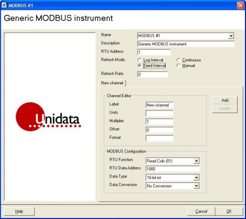
New Modbus registers are added to the scheme using the “Add” button.
Scheme memory limits the number of registers to a total of 70 bytes, providing 35 registers if integers are used or around 15 registers if they are floats or a mixture of the two.
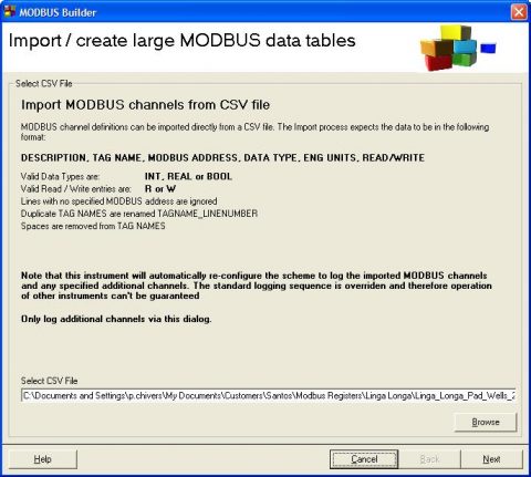
Using the Modbus Builder Instrument in Starlog V4
This option does not allow for Writes, however, it allows for interrogation of an arbitrary number of (hundreds of) Modbus registers by a Starlog V4 scheme.
The Modbus Builder Instrument uses a wizard to configure the instrument.
A CSV (Comma Separated Variable) text file lists and configures each Modbus register in the scheme. Each line of the CSV file configures and individual Modbus register using the following fields.
DESCRIPTION,TAG NAME,MODBUS ADDRESS,TYPE,ENG UNITS,READ / WRITE
The meaning of each parameter is as follows.
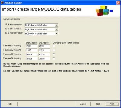
The second wizard screen specifies the Modbus data conversion method to be applied to the received data and the Modbus address mappings for each Modbus function.
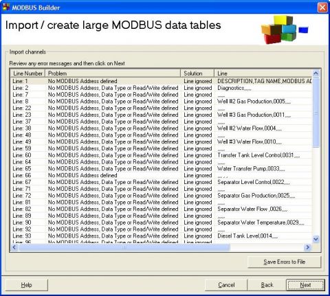
The third wizard screen summarises the results of processing the input CSV file. Blank lines and comment lines generate errors that may be ignored.
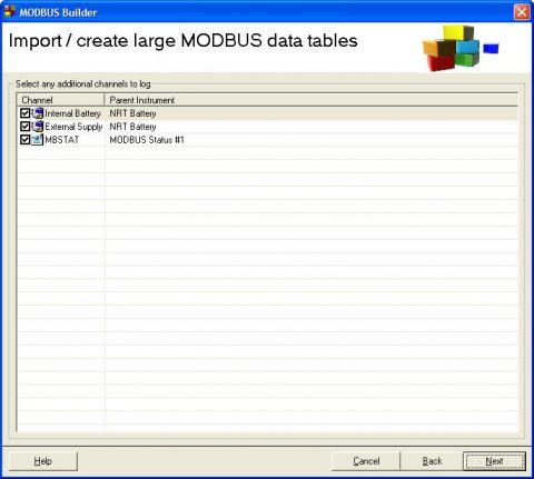
he fourth wizard screen allows for the inclusion of standard scheme data channels into the Modbus Builder scheme. Ticking each instrument allows those data channels to be logged by the scheme.
The fifth wizard screen lists the Modbus registers that have been included in the scheme. This screen is where the Modbus poll rate (Read Rate) and Modbus address are specified.
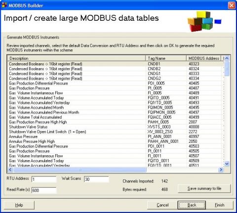
Pressing the Finish button causes Starlog V4 to generate the Modbus data channels for use with the scheme.
Using the Modbus TCP Server Interface
The Neon Server provides a Modbus TCP Server (Slave) interface that may be written to directly by a Modbus Master. E.g. DeltaV
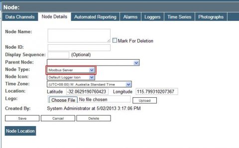
A standard Generic Modbus Instrument scheme must be operating on the NRT. The logger’s Node Type must be set as “Modbus Server” on the Neon Server.
The Neon Server uses the list of data channels in the logger’s scheme to pass Modbus register information to the Modbus TCP Server interface.
When polled by a Modbus Master, the Modbus TCP Server interface immediately returns the last value received from the NRT in the data channel. Data channel values are updated as and when the NRT communicates with the Neon Server according to the NRT’s Communications Frequency.
Modbus Register values written to the Modbus TCP Server interface are transmitted as custom commands to the logger when it next communicates with the Neon Server according to the NRT’s Communications Frequency.
Scheme memory limits the number of registers to a total of 70 bytes, providing 35 registers if integers are used or around 15 registers if they are floats or a mixture of the two.