Environmental Monitoring and Industrial Measurement

Environmental Monitoring and Industrial Measurement
Technical White Paper
Printer-Friendly Version
For Unidata SDI-12 Tester which simplifies the setup and fault finding of SDI-12 sensors in the field and on the laboratory bench please see our product section.
The SDI-12 interface (standard datalogger interface 1200bps) was defined by the USGS (USA – Geological Service) to allow the industry to have an agreed interface standard for sensors which measure water and other environmental parameters. There is an SDI-12 institute which defines standards and versions for SDI-12.
The interface standard allows up to ten (10) SDI- 12 compatible instruments (sensors) to be connected to a datalogger (recorder) which is able to collect readings from the sensors over a two-wire, shared communication bus at 1200 bps. The maximum length of the SDI-12 bus (distance between sensor and recorder) is 65 meters. SDI-12 is not practical for connecting simple, low-cost sensors; it is designed to be used with microprocessor-controlled instruments.
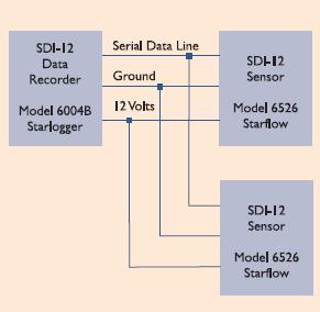
The SDI-12 electrical interface uses the SDI-12 Bus to transmit serial data between SDI-12 data recorders and sensors. The SDI-12 Bus is the cable that connects multiple SDI-12 devices. This is a cable with three conductors: serial data, ground and 12 volts. This figure shows the SDI-12 Bus connecting one data recorder with two sensors. The SDI-12 Bus is capable of having 10 sensors connected to it.
SDI-12 data recorders and sensors communicate by an exchange of ASCII characters on the data line. The data recorder sends a break to wake up the sensors on the data line. A break is a continuous high signal (5 Volts) on the data line for at least 12 milliseconds.
The data recorder then sends a command. The sensor returns the appropriate response. Each command is for a specific sensor. The first character of each command is a unique sensor address that specifies which sensor the recorder wants to communicate with.
Other sensors on the SDI-12 Bus ignore the command and return to low power standby mode. When a data recorder tells a sensor to start its measurement procedure, the recorder does not communicate with any other sensor until the data collection from the first sensor is complete.
A typical recorder/sensor measurement sequence is: