Environmental Monitoring and Industrial Measurement
Environmental Monitoring and Industrial Measurement
Comparison Table Printer Friendly Version
| Options | NRL 3004/3006 | NRL 3008 | NRL 3016 | NRL 3004M/3006M | NRL 3001M | NRT 2018 and NRT 2022 |
|---|---|---|---|---|---|---|
| Description | Industrial NRL 4 Analog Channels (Metal Enclosure) | Industrial NRL 8 Analog Channels (Metal Enclosure) | Industrial NRL 16 Analog Channels (Metal Enclosure) | NRL 4 Analog Channels M-Series (Polycarbonate Enclosure) | NRL Single Analog Channel M-Series (Polycarbonate Enclosure) | NRT Inmarsat Satellite/ 3G/4G |
| Modem | Optional: Cellular 3G/4G/LTE NBIoT Satellite Iridium SBD Satellite Inmarsat BGAN Hughes 9502 Satellite Inmarsat BGAN Sabre Ranger Satellite Certus Iridium RockRemote Satellite Certus Iridium SkyLink | Optional: Cellular 3G/4G/LTE NBIoT Satellite Iridium SBD Satellite Inmarsat BGAN Hughes 9502 Satellite Inmarsat BGAN Sabre Ranger Satellite Certus Iridium RockRemote Satellite Certus Iridium SkyLink | Optional: Cellular 3G/4G/LTE NBIoT Satellite Iridium SBD Satellite Inmarsat BGAN Hughes 9502 Satellite Inmarsat BGAN Sabre Ranger Satellite Certus Iridium RockRemote Satellite Certus Iridium SkyLink | Optional: Cellular 3G/4G/LTE NBIoT Satellite Iridium SBD | Optional: Cellular 3G/4G/LTE NBIoT Satellite Iridium SBD | 2018 Inmarsat Hughes 9502 2022 Inmarsat Hughes 9502 & Cellular 3G/4G |
| Internal Power | No | No | No | Optional 3V6 Lithium D Cell | Optional 2 x 3V6 Lithium D Cell | Optional 3 x 3V6 Lithium D Cell |
| External Power | 9V - 30VDC | 9V - 30VDC | 9V - 30VDC | 9V - 30VDC | 9V - 30VDC | 6V - 24VDC |
| RTC Backup Battery | 3V6 Li Coin Cell CR1620 | 3V6 Li Coin Cell CR1620 | 3V6 Li Coin Cell CR1620 | 3V6 Li Coin Cell CR1632 | 3V6 Li Coin Cell CR1632 | No |
| Instrument Power | 5V regulated 100mA fused | 5V regulated 100mA fused 12V regulated 200mA fused | 5V regulated 100mA fused 12V regulated 200mA fused | 5V or 12V or 18V regulated, 80mA, User Selectable | 15V or 18V regulated, 80mA, User Selectable | 5V unregulated 5mA Max |
| Analog Channels | 4 single-ended (max) or 2 differential (max) 24-bit resolution, 4 user selectable gain ranges | 8 single-ended (max) or 4 differential (max) 24-bit resolution, 4 user selectable gain ranges | 16 single-ended (max) or 8 differential (max) 24-bit resolution, 4 user selectable gain ranges | 4 single-ended (max) or 2 differential (max) 24-bit resolution, 4 user selectable gain ranges | 1 single-ended, 12-bit resolution 0-2.5VDC | 4, 12-bit resolution unipolar, single-ended |
| Digital Inputs | 0 to 5V DC Digital Input | No | 4, Low <1.1V High>2.05V Max 5V DC | No | 0 to 5V DC Digital Input | No |
| Digital Output | 1 - Open Drain FET 30V DC, 250mA max | 1 - Open Drain FET 30V DC, 250mA max | 2 - Open Drain FET, 30V DC, 250mA max | 1 - Open Drain FET 30V DC, 250mA max | No | 1 - Open Collector |
| Counter Channels | 2 x 16 bit, DC to 20kHz free contact or 0 to 5VDC digital input (C0,C2) 2 x 16 bit, DC to 300Hz free contact or 0 to 5VDC digital input (C1,C3) | 2 x 16 bit, DC to 20kHz free contact or 0 to 5VDC digital input (C0,C2) 2 x 16 bit, DC to 300Hz free contact or 0 to 5VDC digital input (C1,C3) | 2 x 16 bit, DC to 20kHz free contact or 0 to 5VDC digital input (C0,C2) 2 x 16 bit, DC to 300Hz free contact or 0 to 5VDC digital input (C1,C3) | 2 x 16 bit, DC to 20kHz free contact or 0 to 5VDC digital input (C0,C2) 2 x 16 bit, DC to 300Hz free contact or 0 to 5VDC digital input (C1,C3) | 1 x 16 bit, DC to 20kHz free contact or 0 to 5VDC digital input (C0) | 1 x 16 bit, 3kHz 3 x 8 bit, 300Hz |
| USB Drive | USB B Port | USB B Port | USB B Port | USB B Micro Port | USB B Micro Port | N/A |
| Base Memory | 7.5MB | 7.5MB | 7.5MB | 7.5MB | 7.5MB | 30KB |
| Memory Expansion | Micro SD Card | Micro SD Card | Micro SD Card | Micro SD Card | Micro SD Card | 8MB |
| Modbus | Single Channel | 2 Independent Channels | 2 Independent Channels | Single Channel | Single Channel | Single Channel |
| SDI-12 | Single Channel 1.3 Compliant | Two Independent Channels 1.3 Compliant | Two Independent Channels 1.3 Compliant | Single Channel 1.3 Compliant | Single Channel 1.3 Compliant | Single Channel 1.3 Compliant |
| HSIO | No | No | Yes | Yes | No | Yes |
| Ethernet | Optional Option E - 0/100 MBit | Yes 10/100 MBit | Yes 10/100 MBit | Optional Option E - 0/100 MBit | No | Yes 10/100 MBit |
| Configuration Port | USB B Port, Micro SD Card and Bluetooth | USB B Port, Micro SD Card and Bluetooth | RS-232 level, 115,200 Max baud rate USB B Port, Micro SD Card and Bluetooth | USB B Micro Port and Micro SD Card | USB B Micro Port and Micro SD Card | RS-232 level, 300-38,400 bps |
| Display | Optional 320 x 240 Colour Resistive Touch Panel | 320 x 240 Colour Resistive Touch Panel | 320 x 240 Colour Resistive Touch Panel | No | No | No |
| Keypad | With LCD option only 5 button membrane keypad | 5 button membrane keypad | 5 button membrane keypad | No | No | No |
| Accelerometer | Yes | Yes | Yes | Yes | No | No |
| Barometer | Yes | Yes | Yes | Yes | Yes | No |
The Neon system collects measurements from Neon Remote Loggers (NRL) connected to field instruments and sensors and transmits these measurements to a central Neon Web-based system for data storage, analysis, data presentation, graphical analysis and reporting and data transfer to other external systems.
The Neon system also provides facilities for remote management of Neon remote loggers via the Neon Web interface to allow for remote reconfiguration, sensor input changes and local program changes thereby minimising trips to the site and reducing cost.
The communication protocol between Neon remote loggers and the central Neon Server is Internet Protocol (TCP/IP) and LoRa LPWAN technology protocol.
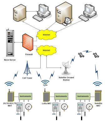
The communications method between Neon remote loggers and the central Neon Server can be any method that utilises TCP/IP, and we support Cell Phone, Wi-Fi, Direct Ethernet, Inmarsat BGAN M2M Satellite, Globalstar Satellite, Iridium Satellite and LoRa LPWAN across public and private networks.
The Starlog 4 software is a desktop application that assists with the setup of Neon remote logger configuration. This software allows for a point-and-click setup of Neon remote logger internal programs, called schemes. Schemes are downloaded to the loggers via a serial interface direct to the logger or uploaded to the Neon Web interface to be downloaded to a logger in the field via the Neon network.
The Neon system is offered to customers based on two options:
1. A customer-owned server model, where the customer purchases a Neon Application Software licence from Unidata and runs that software on their own servers, or
2. A hosted application service model where Unidata provides access to run the system on Unidata secure servers on a fee for service basis.
There is a range of different Neon remote loggers available. While the models may be different, and the interfaces available in various models are different, the basic operation of all Neon remote loggers is the same.
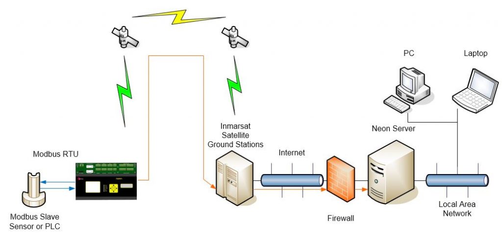
The figure on the right is an example of a Neon installation showing an NRL connected to a Modbus sensor.
Every day the NRL will send, via the Inmarsat satellite network, to the Neon server a “packet” of information containing the data in raw format. The Neon Server then extracts the raw data from the packet. The data is then stored on a secure server until the client accesses the data using a standard Web Browser.
The Neon Server receives, processes, displays, stores and reports collected data in many ways. On top of that The Neon Server also can issue control commands based on pre-set algorithms and issue alarms and notifications via several mediums.
Alarm setpoints can be set up on the NRL units as well as the Neon Server further alarm notifications can be sent via several methods including email and SMS text messages. Alarm triggers can initiate physical actions in the field such as turning pumps on and off or activating other control functions based on the internal program within the NRL.
The Neon system has fully bi-directional communications between the NRL and the Neon Server. This allows for remote diagnosis, remote programming and remote firmware updating for the operation of the remote equipment and thereby reducing costly site visits.
NRL units can be configured to read sensors, log data internally to local memory and push data to the central Neon server at user-settable intervals such as once a minute, every few minutes, every hour, or once a day. Data can be viewed on the Neon Web interface in near real-time from any browser and the comprehensive reporting engine within Neon allows for reporting out to other systems using email, FTP, and web services, either dynamically, every minute, or on a daily, monthly, quarterly or annual basis.
The NRL Internal architecture is shown below.
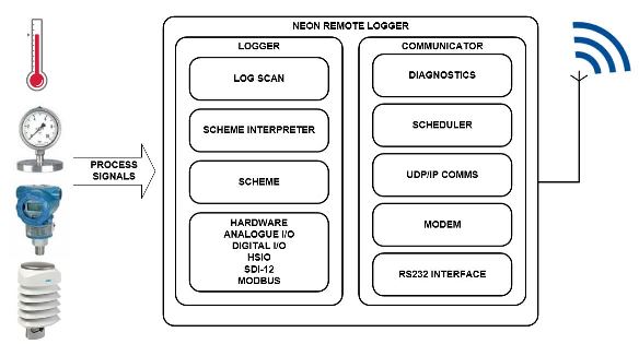
It contains two discrete sections:
1. A LOGGER section where the terminal connects to the field transducers and the logging scheme, scan rates and diagnostics are managed.
The StarlogV4 support software allows a user to generate a logger program (called a scheme) that defines transducer information, logging scan rates, logger interval etc and various engineering unit definitions. These files are called, for example, the LDR and KBD files.
2. A COMMUNICATOR section which deals with communications to the server. This section contains, for example, a scheduler component and the modem component, either a Cellular Network modem or a Satellite Network modem. The communicator manages functions such as the reporting interval, the number of communications attempts per communications session, etc.
The StarlogV4 support software allows a user to generate a configuration file for the Communicator section, called an FPO file in which the user sets the required communications parameters.